Which Tool Can Measure Electrical Potential Between Two Points in a Circuit?

Demonstration analog voltmeter
A voltmeter is an instrument used for measuring electric potential difference between two points in an electric circuit. It is continued in parallel. It ordinarily has a high resistance and then that it takes negligible current from the circuit.
Analog voltmeters move a pointer across a calibration in proportion to the voltage measured and can be built from a galvanometer and serial resistor. Meters using amplifiers tin can measure tiny voltages of microvolts or less. Digital voltmeters give a numerical brandish of voltage by employ of an analog-to-digital converter.
Voltmeters are fabricated in a broad range of styles, some separately powered (east.thou. by bombardment), and others powered by the measured voltage source itself. Instruments permanently mounted in a panel are used to monitor generators or other fixed appliance. Portable instruments, usually equipped to too mensurate current and resistance in the form of a multimeter, are standard exam instruments used in electrical and electronics work. Any measurement that can be converted to a voltage can be displayed on a meter that is suitably calibrated; for example, pressure, temperature, flow or level in a chemical procedure plant.
General-purpose analog voltmeters may have an accurateness of a few percent of full scale and are used with voltages from a fraction of a volt to several thousand volts. Digital meters can be made with high accuracy, typically better than one%. Specially calibrated test instruments have college accuracies, with laboratory instruments capable of measuring to accuracies of a few parts per million. Office of the trouble of making an accurate voltmeter is that of calibration to check its accuracy. In laboratories, the Weston cell is used as a standard voltage for precision work. Precision voltage references are available based on electronic circuits.
Schematic symbol [edit]
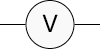
In circuit diagrams, a voltmeter is represented by the letter V in a circumvolve, with two emerging lines representing the 2 points of measurement.
Analog voltmeter [edit]
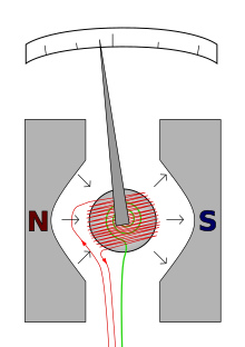
A moving coil galvanometer of the d'Arsonval blazon.
- The red wire carries the current to exist measured.
- The restoring spring is shown in green.
- Northward and Due south are the north and south poles of the magnet.
A moving whorl galvanometer tin can exist used as a voltmeter past inserting a resistor in serial with the instrument. The galvanometer has a scroll of fine wire suspended in a strong magnetic field. When an electric current is practical, the interaction of the magnetic field of the coil and of the stationary magnet creates a torque, tending to brand the coil rotate. The torque is proportional to the current through the whorl. The coil rotates, compressing a bound that opposes the rotation. The deflection of the coil is thus proportional to the electric current, which in turn is proportional to the practical voltage, which is indicated by a pointer on a calibration.
Ane of the pattern objectives of the musical instrument is to disturb the circuit as trivial as possible so the instrument should describe a minimum of current to operate. This is achieved past using a sensitive galvanometer in series with a loftier resistance, and then the entire instrument is connected in parallel with the circuit examined.
The sensitivity of such a meter can be expressed every bit "ohms per volt", the number of ohms resistance in the meter circuit divided by the full scale measured value. For case, a meter with a sensitivity of 1000 ohms per volt would describe 1 milliampere at full scale voltage; if the full scale was 200 volts, the resistance at the instrument'south terminals would be 200000 ohms and at full scale, the meter would draw ane milliampere from the circuit under test. For multi-range instruments, the input resistance varies as the instrument is switched to different ranges.
Moving-ringlet instruments with a permanent-magnet field answer only to direct current. Measurement of Ac voltage requires a rectifier in the circuit so that the curlicue deflects in only ane direction. Some moving-coil instruments are too made with the zero position in the center of the calibration instead of at one end; these are useful if the voltage reverses its polarity.
Voltmeters operating on the electrostatic principle employ the mutual repulsion between 2 charged plates to deflect a arrow fastened to a spring. Meters of this type draw negligible current only are sensitive to voltages over almost 100 volts and work with either alternating or direct electric current.
Amplified voltmeter [edit]
The sensitivity and input resistance of a voltmeter tin be increased if the electric current required to deflect the meter pointer is supplied by an amplifier and power supply instead of past the excursion under examination. The electronic amplifier between input and meter gives two benefits; a rugged moving coil instrument can exist used, since its sensitivity need not be high, and the input resistance can be made high, reducing the current drawn from the circuit under test. Amplified voltmeters oftentimes have an input resistance of 1, 10, or 20 megohms which is independent of the range selected. A once-popular grade of this musical instrument used a vacuum tube in the amplifier excursion and so was called the vacuum tube voltmeter (VTVM). These were nigh always powered by the local Air-conditioning line electric current and so were not particularly portable. Today these circuits use a solid-state amplifier using field-effect transistors, hence FET-VM, and announced in handheld digital multimeters as well equally in bench and laboratory instruments. These largely replaced non-amplified multimeters except in the to the lowest degree expensive price ranges.
Most VTVMs and FET-VMs handle DC voltage, Air conditioning voltage, and resistance measurements; mod FET-VMs add electric current measurements and often other functions besides. A specialized form of the VTVM or FET-VM is the Air conditioning voltmeter. These instruments are optimized for measuring AC voltage. They have much wider bandwidth and better sensitivity than a typical multifunction device.
Digital voltmeter [edit]

Two digital voltmeters. Notation the 40 microvolt difference between the 2 measurements, an offset of 34 parts per million.
A digital voltmeter (DVM) measures an unknown input voltage by converting the voltage to a digital value and then displays the voltage in numeric form. DVMs are usually designed around a special blazon of analog-to-digital converter chosen an integrating converter.
DVM measurement accuracy is affected by many factors, including temperature, input impedance, and DVM power supply voltage variations. Less expensive DVMs often have input resistance on the order of x MΩ. Precision DVMs can have input resistances of 1 GΩ or higher for the lower voltage ranges (e.m. less than xx 5). To ensure that a DVM's accuracy is within the manufacturer'southward specified tolerances, information technology must exist periodically calibrated confronting a voltage standard such as the Weston cell.
The showtime digital voltmeter was invented and produced by Andrew Kay of Non-Linear Systems (and later on founder of Kaypro) in 1954.[1]
Simple AC voltmeters employ a rectifier continued to a DC measurement circuit, which responds to the average value of the waveform. The meter can exist calibrated to display the root hateful square value of the waveform, assuming a fixed relation betwixt the boilerplate value of the rectified waveform and the RMS value. If the waveform departs significantly from the sinewave causeless in the calibration, the meter will exist inaccurate, though for unproblematic wave shapes the reading tin can be corrected by multiplying past a constant factor. Early on "true RMS" circuits used a thermal converter that responded only to the RMS value of the waveform. Modernistic instruments calculate the RMS value by electronically calculating the square of the input value, taking the boilerplate, and so calculating the foursquare root of the value. This allows accurate RMS measurements for a variety of waveforms. .[2]
See as well [edit]
- Ammeter
- Grade of accuracy in electrical measurements
- Electric measurements
- Electrometer
- Electronic examination equipment
- Metrology
- Multimeter
- Ohmmeter
- Potentiometer (measuring instrument)
- Solenoid voltmeter
- Voltage divider
- Measurement category
References [edit]
- ^ Markoff, John (v Sep 2014). "Andrew Kay, Pioneer in Computing, Dies at 95". Obituary. New York Times. Retrieved 7 September 2014.
- ^ "What is Truthful RMS Measurement? RMS Vs True RMS". Electric Volt. 2018-09-19. Retrieved 2021-10-14 .
External links [edit]
| | Wikimedia Commons has media related to Voltmeters. |
- DC Metering Circuits chapter from Lessons In Electrical Circuits Vol one DC complimentary ebook and Lessons In Electrical Circuits serial.
Source: https://en.wikipedia.org/wiki/Voltmeter
0 Response to "Which Tool Can Measure Electrical Potential Between Two Points in a Circuit?"
Post a Comment